Monday 14 March 2016

Project Supercub

One 1982 Honda C70
Because everybody needs more than one project, I've initiated Project Supercub.  I've acquired a 1982 Honda C70 which will become a sleek & mean street machine.

Honest!


So, here's the starting point.  She's a lovely blue pizza delivery bike with 34 years behind it and hopefully many more years ahead of it under my stewardship.


Complete with pizza box and L-plate
First things first, let's get stripping and see what we're dealing with.

As you can see, the frame looks to be in excellent condition.  There's some rot at the end of the mudguard, where they all go, but that's to be expected and is also completely irrelevant for this build.


Mostly stripped and in bloody good nick
All structural elements are in fine fettle and she looks like she'd scrub up okay with a bit of wire wool and a respray, but that would be far too easy!
My tame technician getting chop-happy
Further stripping (not photographed, unfortunately) has seen the fuel tank (pretty much mint), front wheel, front fender, handlebars & headstock, centre stand, forks and wiring loom removed.  In fact, everything removable has been removed.

Next up: removing the non-removables.


De-seaming
A rusty gash
As previously mentioned, that rusty mudguard has been whipped off, leaving a much sleeker and curvier rear end (albeit one with nowhere to mount any lights or a number plate, but I'll figure something out...)

Then there's that unsightly seam running from the back of the fuel tank all the way down the spine of the bike.  Yuck.  Let's get rid of that, please.

And that's about all the progress for now.  Once the seam is welded up and ground level, the frame, tank, forks, swinger and sundries will be heading off to be dipped, blasted and electro-plated and then...  Um...  Well, I'll just have to see how it goes.  There'll be some paint.  And I've bought a ridiculous amount of lighting options.

Many, many thanks to the very talented Ben Thompson at Majestic Motors for his time, advice and skills so far.
A lighting option

Stay tooned.

Wednesday 10 September 2014

Volvo 850 T-5 Distributor & Rotor Arm Replacement

It's been a while since I used this blog and I'm afraid this post is slightly off topic, but relevant to Volvo maintenance.  My 'other' car is another 850; a T-5 estate.  After a recent trip to Wales (see http://www.chroniclerally.co.uk/rally---wales.html for details) I had started experiencing running problems.  A slight misfire/hesitation whilst under heavy load.  Initially blaming supermarket petrol and thinking I'd got some water in the system, I put a couple of bottles of Wynn's Dry Fuel through a couple of tanks of V-Power, but the issue remained.

Talking through the symptoms with a former mechanic friend, he suggested taking a look at the distributor cap & rotor arm, which I did and this is what I found:

Manky Cap
As you can see, the contacts are pretty poor and there are trace lines where the spark has been taking the scenic route instead of heading for the plugs.

And the rotor arm (below) didn't look much better, so I hit up German & Swedish, handed over £24 and went home with some new bits.

Rank Rotor
The next few paragraphs will be about the removal of the old components.  There's not much about fitting the new ones, but as the book of lies always says, "refitting is the reverse of removal."

That said, I will mention anything I caught which is worth noting, but there's no images of the refit process.

Although this post is based on the process for a T-5 engine, the instructions will work for non-turbo 5-bangers just as well.  You n/a owners will actually find the cap is more easily accessible due to the reduced amount of plumbing involved.

It's in there somewhere...
First things first, where is it?  You'll find it dangling off the 'back' of the inlet camshaft.  In English, that means it's the opposite end of the engine to all the pulleys (which are next to the V in Volvo in this image) and it's in the top corner of the engine, nearest the front of the car.  Handily, that means it's squished between the engine and the airbox (the bit that says 'TURBO' in the picture).  On a turbo model, that also means it's under that whacking great pipe running over the top of the motor.

Separation isn't so hard
The first thing to do to access the distributor is to remove the airbox.  That's a relatively easy task, so don't give up yet!

Before yanking it out, you'll want to do three things.  Firstly, you'll want to disconnect the air intake from the very front of the car where it disappears into the grille next to the radiator.  This is easily achieved by separating it along the seam between the ribbed/flexible part to the right of the image and the plate-like bezel around the front part.  This is probably more evident when you're looking at it in real life!

Pesky Pipe
Secondly, you'll want to disconnect a wee rubber hose from the intake pipe.  It's on the bottom of the pipe, just behind the jubilee clip holding the MAF sensor in place.  It has a blue band around it for accurate identification purposes.

This will then allow you to unclip the top of the airbox and fold it out of the way.  Be careful to check that nothing else is clipped to the box (like the main ignition lead from the coil, for instance!)

Clippy Clippy!
Unclip all of the retaining clips which hold the top half of the box in place - I think there are three on the front side, a further three on the back side and another one on the end where the actual distributor is (remember what we're trying to achieve?)

Once they're all unclipped, lift the top half off the box, but try to keep the air filter in the bottom half as you do so - it will want to come with you, but let it down gently.  I find the top of the box will hook neatly onto one of the suspension strut bolts where you can forget about it.

Now we're getting somewhere
This is probably a good opportunity to take a look at the condition of your air filter.  Mine could probably do with a change, but I just beat the dust out of it and will get around to replacing it another time.

The last of the three things then is to remove a sensor mount from the side of the bottom half of the airbox.  It's easier to get to with the top removed, which is why it's the last thing to do.

(Un)screw this!
I'm afraid this is about the clearest picture I could get, but you should be able to make out the two screws holding the greyish thing to the side of the airbox.  The screws are T-25 self tappers, so you'll need a T-25 Torx bit and it's probably easiest to loosen them with a ratchet spanner.

You also may benefit from disconnecting the sensor from the wiring loom by depressing the little clip on top of the connector and pulling it away (towards the front of the car).  You can let the sensor dangle, as the rubber hoses will keep it nearby.

Breathe Relieved
At this stage, you should simply be able to wrangle the airbox free.  It is held in place by two clips at the engine end and a rubber grommet in the inner wing.  Giving a decent upward tug at the engine end should liberate it from the clips and pushing the whole thing towards the engine should free it from the grommet.

This will completely free the airbox, but there's a slight caveat in that I actually have a slightly smaller battery than standard in my car.  That means you might have to either remove the battery or unclip the inlet pipe from the bottom of the airbox (from inside the box, under the filter) before you can actually set it free.  Please do let me know in the comments whether you had to do this and which method was easiest - I couldn't get the pipe unclipped when I tried, but I didn't try very hard!

With the airbox removed, you should have all the working space you need to actually remove & replace the dissy cap & rotor arm.

Space: The Ultimate Luxury
I am not a number!
I know I've already been teaching you to suck eggs, but one thing I think is rather important before you go any further is to label the ignition leads in order to make sure you put them back on in the correct layout for the firing order.  The firing order of the Volvo 5-cylinder modular engine is 1, 2, 4, 5, 3 and the lead for cylinder #1 is the one in the roughly ten o'clock position when you look at the cap end-on.  Again, looking end-on, the firing order is anticlockwise, so I just used the end of a screw to scratch the numbers into the rubber of the leads.  You may choose to use Tippex, a pen, or some chocolate.  You may also choose to label them something else.  A, B, C, D, E, for example.  Or maybe Roman numerals.  Or α, β, γ, δ, ε.  Or perhaps Klingon.  It really doesn't matter, as long as you make sure you put them back in the same order when you're done.

Bare Terminals
With the leads labelled, you can go ahead and pull them all off.  They will generally stay out of your way, so you probably won't need to tie them up, but there's no harm in it.

It's probably wise to keep the coil lead away from the battery, so you might want to tie that one up.

As you can hopefully see in the image, just three bolts stand between you and removal of the cap.  Due to the still marginal access, it's probably easiest to use a screwdriver to take them out.  The original Volvo ones are slotted for a flat blade driver.  The replacement item I bought also allow the use of posi-drive, which is nice.

Hello Roto!
The bolts don't come out all the way, so don't worry about dropping them, but do try to keep the cap level & supported until all three bolts are loose.  Simply pull the cap straight off (towards the void you created by removing the airbox) to expose the rotor arm.

The last time I replaced a dissy & rotor was on an Austin Metro, so I was pleasantly surprised to see a wee plastic cap inside the Volvo (Bosch) cap.  I presume this is to help prevent oil spraying all over the inside.  My engine could do with a few seals replacing, so there's oil everywhere, but the cap was reasonably clean inside.
Cap Doffed

You'll need to remove this inner cap to get the rotor arm off, but it's not actually fixed in place.  You just need to pull it away from the base and angle it over the rotor arm to expose the three bolts holding the arm in place.

In typical Swedish fashion, a third type of bolt (after the Torx self-tappers and the slot-cut bolts of the distributor cap) hold the rotor arm on.  This time, the bit I needed from the box was a 3mm allen bolt bit.  Oddly, the replacement part came with 4mm allen heads.

And you're done!  Well, everything's removed and I've run out of photos, but it's the same thing.  Fitting is the reverse of removal, but here's a couple of pointers:

  • When tightening the bolts on the arm and the cap, put them in loosely to start with to make sure there's wiggle room in case one doesn't want to go in the hole.  Then, working clockwise, tighten them to thumb-tight.  Clockwise again, nip them up tight-ish.  Finally, clockwise again, go around and give it a bit of effort.
  • The original distributor cap came with a plastic black cover.  If you want to reuse this, you will need to remove the three bolts from the cap by pulling them up against the inside of the cap and then unscrewing them.  You will also need to put the bolts for the new cap through the plastic cover first.  Be warned though, the plastic cover didn't fit my replacement cap, so it's probably only suitable for a genuine Volvo replacement part (which probably comes with a replacement cover as well!)
  • Before trying to fit the new cap, wind the bolts into the three bolt-holes until they slide through.  It's just easier, trust me.
  • The 'tallest tower' on the cap is for the ignition lead for cylinder #1 which is at roughly the ten o'clock position.  That should get you lined up close enough for the bolts to do the rest.
  • When refitting the airbox, remember to reattach the sensor you removed earlier (press the clip to plug in the connector) before you put the top half back on, as access is limited.
  • Also remember to reattach that wee rubber hose to the top half of the airbox after you've clipped it back on.
Please do let me know about any comments or corrections and I hope you've found this useful.

Friday 15 June 2012

Suspension Before & After

Just a quick post to show a couple of pictures of the car before and after the suspension was lowered.


Before (and looking rather sad)


After.  Not a huge difference, but definitely feels better.
I'll chuck some more updates in once the BTCC decals arrive and the boot spoiler is installed.

Monday 11 June 2012

Slammed Suspension Set-up

Here's the latest instalment of the preparation for the Chronicle Rally.  Yesterday, I took the car to my friend and team mate's workshop in Coventry (about 25 miles away) to fit some 40mm lowering springs I had acquired for the car.  For those viewing this blog as a 'how to' resource, I guess you could classify this as a how to lower the suspension on a Volvo 850 or how to replace the front and rear suspension springs on a Volvo 850.


Shameless search engine plug out of the way, here's the meat!


First up, the car goes up in the air.  I really need to get hold of one of these hydraulic car ramps; they don't half make life easier!  This is a good opportunity to take a decent look at the state of affairs underneath the car, so we give all the  nuts & bolts we intend to undo a good scrub with a wire brush and a liberal spray with penetrating oil.


While the oil is soaking in, we give everything a good yank to make sure it's all tied together right and we give the exhaust a good thump to make sure the baffles are still solid.  It's also an opportunity to check for any rust or any fluids that shouldn't be there.  The underside of the engine is completely dry, which is a good sign for an 18 year old car with about 160,000 on the clock*.  All the seals/gaskets are healthy.


* I say "about 160,000" because I'm not entirely sure how many miles the car has done.  The odometer reads 151,950 but I've gone through nearly three tanks of fuel since taking that reading and it's still the same!  I reckon that's close to 1,000 miles, but I don't know how long the odometer has been broken.  It's at least 153,000 miles, but probably many more.


Everything looks good, the (original) exhaust is solid, there's no rust, no damage, no fluids, so we proceed with the task at hand.


We start on the front, as this is the bigger job to get out of the way, so off come the front wheels.  Hopefully you know how to do this, so I didn't bother taking any pictures or writing a procedure for it.


What?  You want to know?  Er, okay.  Just undo the five bolts holding each wheel on and pull towards you.  Righty tighty, lefty loosey!


Okay, wheel off, we can now get down to business.  First, remove the nut from the bracket on the strut just above the brake disc.  This is the end of the anti-roll bar.


Next, further down the strut, there are two bolts holding the shock absorber (that's a damper to you Yanks) to the hub.  These need to come out.


Once these bolts are out, the only thing truly holding the strut in place is the top plate that bolts through the inner wing.  So down comes the ramp, up comes the bonnet and out comes the air gun (I want one of these as well, but that also means acquiring a compressor - slightly outside my budget at the moment!)


Top mount, inner wing
There are 3 nuts securing each strut through the inner wing.  We remove two nuts and put them somewhere safe (preferably not on the plastic housing beneath the windscreen, as there are some lovely drainage holes to lose them down!) but only loosen the third - we don't want the strut falling out at this stage, as it could pull the drive shaft out and put is in a whole world of hurt!


The car goes back up in the air; not too high, as we still need to be able to reach that last nut.  We bring in a stand to support the wheel; just something placed under the brake disc to take the strain.


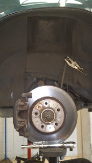
Missing: One suspension strut.
If found, replace with lowered
spring and reattach.
Disconnect the ABS sensor from the back of the hub.  This helps the strut pull clear once loose.  Now the third nut can be removed from the top mount, the ARB pulled clear and the strut pulled off the hub.  Depending on the age, corrosion, etc. the strut might need quite a yank to free it from the hub, but it should just fall through the inner wing at the top.


Voilà!  The strut is out.  Now all we need to do is remove the spring, replace with the new one, shove it back in and put it all back together.


With the strut on the bench, use some correction fluid (Tip-Ex et al) or a marker pen to mark up how all the components align.  This is very important, as you won't know how to put it back together correctly otherwise!


Everything marked up, chuck the whole lot in a spring compressor (I think I just need an entire workshop...) and wind it up until the spring becomes loose from its top and bottom mountings.  Don't worry too much if the rubber dust shield gets pulled away in the process, just remember to reattach it before putting the strut back on the car.  It is a fiddly job, but not too bad.
Blurry-cam says "Feeling depressed?  Fear not, you'll soon spring back!"


At the top of the strut there is a nut holding the top mount assembly together.  Undo this, remove what you can (remembering what order/orientation everything was in) and a new four-leaf clover shaped nut will be revealed.  Undo this as well (you may need some mole grips on the centre shaft to stop the whole lot spinning when you try to undo this) and the whole strut should pull through the bottom of the spring.  Please remember what order everything came off in.  I know I've already said that, but it's important!


Now the strut is out, slowly unwind the spring compressor until the spring comes loose.  Lift the old spring out and compare it with the new spring to decide on orientation.  On the 850, the bottom of the spring turns in ever so slightly at the end of the last coil.  Drop the new spring into the compressor and wind it up just enough to hold the spring firmly in place, then offer up the strut.  Pull the strut through as far as it will go (the shocker should extend quite a bit with a little persuasion) then continue winding up the spring compressor until you can get the top mount components back on.


Loosely refit the top of the strut, then make sure everything is aligned with your earlier markings.  Once everything's aligned and feels securely in place, tighten it all up and unwind the compressor until you can lift the assemblage out again.


Job jobbed.
As the book of lies tells us, replacement is the reverse of removal.  The only thing I'd add is a suggestion to cover all of the bolts in copper grease to ensure they are nice & easy to get off at a later date if required.  Otherwise, replacement really is quite straight forward and should occur more easily than removal due to all the nicely freed up parts.


Just for comparison.
That's the front essentially done, so time to move on to the rear.


Leave the wheels on!


Seriously, the rear end is a much easier affair.  You can leave the wheels on; in fact, you will want them left on.  You'll see why shortly.


Up the ramp goes again, high enough so we can easily get underneath the car.


Once under the rear, the suspension set-up is quite clear to see and it's simple.  Some might say basic.  The rear springs reside in cups on the end of what is essentially a trailing arm.  Just forward of these cups are the shock absorbers, the bottom of which attaches to the aforementioned arm by a single nut.  This is the first task; undo this nut, then pull the shocker away from the frame.


Spring cup and shock mount.
Next up, there is a nut in the centre of each cup - underneath.  This nut needs to be removed to release an inner cup that clamps the spring down.  Now, this is where we came a little unstuck on my car.  The off-side nut came out without too much persuasion, but the nearside one didn't seem to want to cooperate.  Worse than that, the thread it attaches to seemed to be pressed into the 'sub-cup' and the pressing was simply turning independently of the rest of the assemblage.


A couple of spot welds later and all's fine!


Once the nuts are removed, we need to get the 'sub-cups' out of the way.  We don't want the pinging off when we pull the springs out, but they unfortunately have to come out between the coils of the spring.  With a bit of fiddling, the will force through.


We actually missed this part out, but I'm going to write it here so you don't forget about it.  Get your Tip-Ex/marker pen out again and mark the locations of the rubber mounts at the tops of the springs.  It might not matter, but it's always best to put things back where you found them, especially when they've had 18 years and 160,000 miles to settle into that location!


Reassembled Rear.
Now comes the fun part.  Find your two fattest friends and ask them to hang off the rear wheels.  I'm not kidding!  With the shocks detached, the weight of about 100kg hanging off each wheel will be enough to release the tension on the springs so they can simply be popped out!  This is why you don't want to remove the wheels; brake discs aren't as comfortable to dangle off!


Compare the old & new springs again to determine orientation, then pop the rubbers into the top of the new springs and commence operation Monkey Dangle again.  Insert the new springs, slip the 'sub-cups' back in and tighten the troublesome nuts back up.


Lastly, the shocks need hooking back up.  This might require a little assistance from those stands we used to support the front wheels earlier.  Just give them a bit of a lift until the hole lines up, then just pop the end of the shocker on and tighten up the nut.


After putting everything back together, it's a good idea to to a tracking & alignment check.  We didn't think this would have changed much and only really checked it because the equipment was to hand.  It was way off!  I'm afraid I didn't document this part, but a little fettling behind the front wheels soon straightened everything out.


And there you have it.  Replacing the suspension springs on a Volvo 850 is as easy as that!


I'll try to get some before & after pics added here at some point.  I've got a before, but didn't get a chance to snap an after.


One thing to note, the ABS warning light came on after all of our fiddling near brakes.  I was worried about this, but as soon as I started driving the car the light went out.  The pump always primes the first time you hit 10mph, so I guess the system just does some diagnostics at that point as well and decided everything was okay.


Another update to the story, too small for its own post:


While up on the ramp, we also used the opportunity to do an oil & filter change, so that's another job out of the way.


That's not a reflection of the box...
We've had rather a lot of rain here recently (actually, it's been the wettest & coldest June I can remember!) and I've noticed that the driver's windscreen wiper wasn't clearing the screen at the top two or three inches of its arc.  No biggie, but I wanted to sort it.  Having stopped the wiper at the top of its arc, I could see it wasn't just not clearing the water, it was completely missing the screen!


While the car was in the workshop, we tried a few spare wipers Pav had lying around.  No joy.  Turns out it was the actual wiper arm.  Somehow, while the car had been stood, the arm had 'adjusted' itself so that it was nowhere near the windscreen at the top of its sweep.  That's in inverted commas because there is no adjustment!  We couldn't figure out how it had got like that, so we turned to brute force & ignorance and simply bent the upper part of the arm to put it closer to the screen.  It's a bit banana shaped now, but it does the job and that's good enough for me!


Lastly, we read out the ECU codes again, noted them down, then reset them all.  This has extinguished the Lambda light again and it hasn't come on since (so far).  My next job is to try to work out exactly what these codes mean, as the documentation I acquired from the Internet seems to be lying...


Thanks to my team mates Pawel Dabrowski for the use of the workshop, the welding, the replacement wiper and his time, and Matthew Weller for his Volvo experience which amounts to an inside-out knowledge of the 850!


Also thanks to everyone following this blog.  I hope you find it entertaining, interesting and/or informative.  Please stay tuned for more!

Friday 18 May 2012

Behold! A New Post!

Yes, I apologise for the frankly epic hiatus on here since my last update.  Sorry about that.  It seems whenever I've had time to work on the car recently, the weather has had other plans!


Well, there's good news.  Last weekend brought a couple of hours of dry weather.  Just enough for me to strip the brakes down again (I'll not bore you by repeating the whole procedure here!) and realise that the handbrake actually appeared to be working!


Hastily, I chucked everything back together, adjusted the shoes and yanked on the brake.  Solid as a rock!  Woopah!


I booked it in for its MOT immediately and got the good news this afternoon that it had passed.


As soon as I got home, I got straight on the Internet and taxed the thing as well.  Directly the tax disc arrives, I will be fully legal and the real work can begin.


In celebration, I bought the car a treat:


"Remove Before Flight" Keyring
I thought these keyrings were perfect for the theme of the car when we take it on the Chronicle Rally.


No, the theme has nothing to do with aircraft, but these tags are used elsewhere and have become something of a de facto tag for reminding engineers to remove whatever they're strapped onto before the vehicle/machine is started up.


They are actually used in touring cars (in the throttle inlet, for instance) so I figured they were perfect for out touring car theme!


Although I've got no more procedures to show you at the moment, getting the MOT is a huge step forward.  It means I can use the car on the public road, which in turn means I can take it to a workshop, etc. for making the upcoming work much easier.


Speaking of which, upcoming work includes the following:


  • Front brake discs & pads renewal
  • Oil & filter replacement
  • Coolant refresh
  • Brake fluid substitution for high temperature racing fluid
  • 40mm lowering spring kit
  • BTCC decal kit
  • Probably lots of ancillary work along the way!
Stay tuned right here for all this and more!  (Did that sound like an American TV announcer, or what?!)

Seriously, I promise there will be some marginally more interesting content in the forthcoming weeks.  There's a lot to do before the rally and I intend to blog about all of it.

Following that, there will hopefully be more blog posts about the road car's transformation into a racer!

Good stuff.  Subscribe to get new posts first.  Much love.

Monday 16 April 2012

I'm Still Alive!

Rumours of my disappearance have been grossly exaggerated!


As the blog has been rather barren for a while, I thought I ought to post something, even if there's nothing exciting to post!


I have received the handbrake parts I was waiting for, although I have a couple of cables with different part numbers on them.  My supplier wasn't sure of the correct part, so he sent me both and asked me to send the wrong one back to him, which is much better than taking a guess and risking getting it wrong!


Anyway, I'll reserve the work I've done on this so far for the next update - that way, there's an entire post dedicated to the replacement of the handbrake cable on a Volvo 850 for anyone who's looking for it!


Ed.

Wednesday 4 April 2012

Minor Update

As I haven't posted anything in a while, I thought I should give a minor update on what's going on with the car at the moment.


Begin Update:


Not a fat lot!


End Update.


I've essentially done nothing with the car since the last update, but I have managed to ascertain that the nearside handbrake cable is shot.  This is the only reason for the brake not to work when everything is moving freely enough and the offside brake does work.


I have placed an order for a new cable and am just waiting for it to come in before I can begin the next challenge.  Having never done one of these before, I am a little bit apprehensive.  I have a suspicion this job will be as highly sprung as the shoe replacement in my last post, so I'm not really looking forward to it. It also means dismantling some of the car's interior, which I don't have a good history with - it usually doesn't go back in the right place...


Other than that, I can report that another package landed on my desk yesterday - a full set of 40mm lowering springs.


The spring fitment will be carried out once the car has got a full MOT on it and I will try to document that part as well.  I will be enlisting the help of a friend with a workshop for that job, though...


And that's it for now.  No exciting pictures, no lost limbs and no blue language.  The only other news is that the ferry and all the hotels are now booked for our little adventure in July, so there's no backing out now!


Next update will hopefully end in a working handbrake...